
Proof Of Afterlife By Information
4.2 Section Two: Memory Addressing
4.2.1 Memory Address Building Blocks
The actual wiring of computer memory is called an address bus. An address bus is the wiring that gives each specific memory location its own unique address. The address bus allows the computer to access one specific mailbox from among millions of available mailboxes.
There are two basic elements that make up an address bus as shown here:
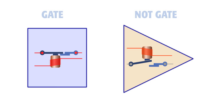
1. The first element is the Gate shown left. When power is applied to the input the electromagnet switch is closes and current is allowed to pass. Conversely, when current is no current is applied the electromagnet opens and current cannot pass. We shown this gate is a square.
2. The second element is the NOT Gate. When power is applied to the input the electromagnet the switch is opened and current is stopped. Conversely, when no current is applied to the electromagnet the switch closes and current is allowed to pass. We show the NOT Gate as a triangle.
The address bus is made up from just these two elements. The square opens with current. The triangle closes with current and vice versa. Creating an address bus is a matter of arranging these two building blocks into a matrix of binary numbers.
4.2.2 Memory Address Bus
This illustration shows a section of an eight line address bus. The squares and triangles are arranged like numbers in a sequence. A square represents a one and a triangle represents zero. Each row of gates represents a unique binary number manifested in hard aware.
The top row row is eight blue squares. This can be thought of as the memory address 11111111. The second row is 11111110. The third row is 11111101 and so on. The elements are arranged in a array so each row defines a unique number or memory address as shown:
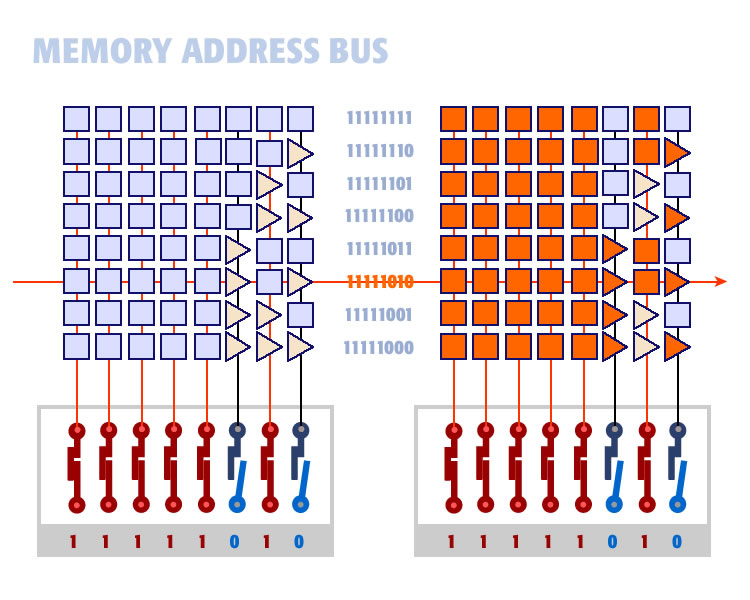
We are going to enter a binary number in the address register as shown on the lower left of the diagram above. The number we enter is 11111010. We enter it by opening or closing switches. In this case we close the first five switches, open the sixth, close the seventh, and open the eight.
The result is turning ON lines 1 to 5, and 7 and turning OFF lines 6 and 8.
On the right you can see how our memory matrix reacts to current on address lines:
1. All squares turn ON when current is applied.
2. All triangles turn ON when no current is applied.
Gates turned ON are shown in orange.
As you can see only one memory address matches the binary number entered on the bus. That is memory location 11111010. It is the only combination of squares and triangles that are lit allowing current to get all the way from left to right. The memory bus applies current to that one memory address only.
The arrangement of gates is how computers store and access data to and from unique memory addresses.
4.2.3 Full Memory Bit
This illustration below shows a full implementation of a computer bit. It shows the addition of an address line and a read/write line:
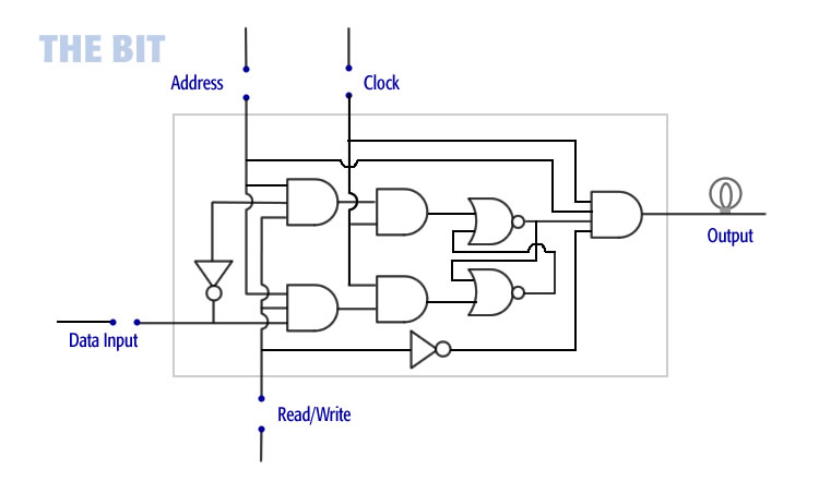
This is a computer bit. Here is how it works:
To Write Data (shown left):
1. Turn the address line ON
2. Turn the read/write line ON
3. Turn the clock line ON
4. Enter your information on the data line (ON for one, OFF for zero)
The illustration on the left shows the address line ON, read/write line ON, and data line ON. These AND together. The input state (ON or OFF) gets through to the second AND gate where it is ANDED with the clock line. When the clock line is ON the data sets into the bit.
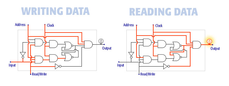
To Read Data (shown right):
1. Turn the address line ON
2. Turn the read/write line OFF
3. Turn the clock ON
The address line, state of the bit, read/write line, and clock line are all ON. They AND together. This places the state of the bit (either ON or OFF) on the output line.
4.2.4 Memory Matrix
Memory is the same bit repeated thousands of times arranged into a matrix. The illustration below shows 16 bits arranged into a four by four memory matrix. Each bit is identical. The illustration shows how bits are connected via the address, data, read/write, clock, and output lines.
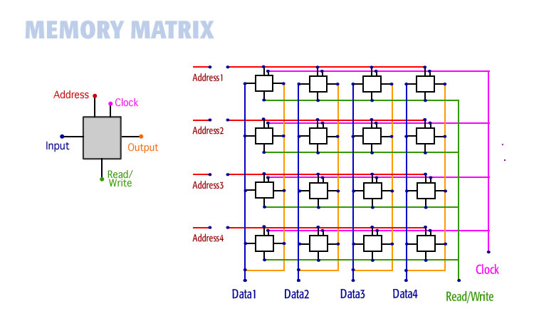
Reading data is a matter of turning ON or OFF the various lines. For example the read/write line tells the computer whether you are reading data from a bit or writing data to it.
This 16-bit memory shown above is accurate. Memory in a computer is like this but there are more bits, address lines, and data lines but the logic is identical.